Special Reports
2013 Quarter 4 Issue 17
Solutions of Central Cooling System
What’s central cooling system?
Central cooling system, just as its name implies, is a system for centrally providing chilling water to devices in a particular area. It’s built by the following way: choose appropriate cooling devices and project integrated layout according to parameters which are obtained by calculating basing on information of the required temperature, pressure, flow of cooling water and plant layout, etc.

Central cooling system, just as its name implies, is a system for centrally providing chilling water to devices in a particular area. It’s built by the following way: choose appropriate cooling devices and project integrated layout according to parameters which are obtained by calculating basing on information of the required temperature, pressure, flow of cooling water and plant layout, etc.
Main features
•Be able to precisely control chilling water temperature to adapt to different working conditions to meet demands.
•Compared with using of several single water chillers, central cooling water system can save cost.
•The main machine of central cooling system is usually placed outside the workshop, which can ensure low noise inside the workshop and good working environment.
•Save inner space of workshop. Water chiller of single machines is placed inside the workshop, which occupies too much precious space of factories. However, for central type, machines are usually placed in a particular area; few pipes can be seen, since all pipes are placed in the upper of the workshop or buried in the trench to make the workshop clean and tidy.
•Ensure continuous production even when the pump is with failure. The central cooling system is usually equipped with multiple pumps. When one of those pumps is broken, spare pumps can immediately be used for production, which ensures the continuous production.
System structure
Application of main water cooling machine
Application of main water cooling machine should be based on comprehensive consideration of factors, like the overall configurations of system, cooling requirements, the environmental and geographical conditions of workshop, equipment cost, and noise, etc.
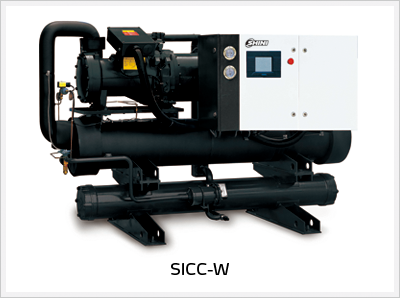
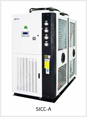
Generally speaking, water cooled central water chiller is suitable for places with plenty of water and moderate ambient temperature. Water cooled central water chiller requires a cooling tower to work with for conveniently cooling water chiller unit with good cooling effect. However, it’s not applicable when environment is of too low temperature and easy to freeze. Air cooled central water chiller doesn’t require cooling tower. It cools refrigerant of high temperature via outside air so that it cuts the cost of cooling tower. It also can control cooling effect through controlling air volume when the ambient temperature is too low. However, its noise is larger than the water cooled one. Besides, it’s not suitable for situations where the ambient temperature is quite high.
Cooling Capacity Calculation
Cooling capacity calculation, which is the start for calculation of all parameters, structure design and select of device, is the key point of central water cooling system. For injection plastics molding factories, cooling capacity calculation usually consists of two parts:
•Rapid cooling of molds
•Oil cooling of injection molding machine’s hydraulic system
Rapid cooling of molds
Most time of injection molding is for cooling molding products. Besides, all cooling water pipes of molds are placed quite near to the molding chamber of molding products to achieve high efficiency of cooling. Therefore, one mold is a heat exchanger which is used for taking heat away from molding products of high temperature by cooling water to improve molding speed. If molds are not equipped with hot runner system, it can calculate heat as the following formula:
Q1=M × S × T × δ
Q1=Refrigerant capacity(kcal/h)
M=Plastics consumption(kg/h)
S=Plastics specific heat(kcal/kg℃)
T=The temperature gap between the melt temperature and the product demolding temperature, which usually is 200℃.
δ=Safety factor
δ stands for safety factor, which is usually between 2.0 and 3.0. When choose air-cooled water chiller, it’s necessary to choose the bigger one on S. For bottle blowing machine, S may be 4.0.
If molds are equipped with hot runner, the refrigerating power should be increased accordingly. The increment is usually 0.6~0.8 times of hot runner power.
Cooling of injection molding machine
For injection molding machine, its refrigerant capacity is related to the motor power and molding cycle of hydraulic molding machine. It can be calculated according to the following formula:
Q2=P ×δ
Q2=Refrigerant capacity(kcal/h)
P=Motor power(kW)
δ=Factor
Usually, δ is ranging from 0.35 to 0.5. The value of 0.35 is suitable for common molding cycle (the molding cycle is greater than 10 seconds). The value of 0.5 or more is suitable for rapid molding cycle (the molding cycle is between 3 and 10 seconds).
Circular water capacity
The cooling water flow that a mold need is related to the heat that the mold needs to release and the temperature gap between inlet and outlet cooling water. It can be calculated according to the following formula:
Chilling water flow (Chilling water refers to the circular water of room temperature that the water chiller asks from the outside.):
L=(Q+P)÷(C×△t×D)÷1000
L=Required capacity of cooling water(m3/h)
P=Capacity of compressor (kW)
Q=Refrigerant capacity(kW/hr)
C=Specific heat of water 1kcal/(kg•℃)
△t=The temperature gap between inlet and outlet water, 5℃
D=Density of water kg/L
the cold water flow (cold water refers to the circular water of low temperature that the water chiller supplies for onsite production)
L=Q÷(C×△t×D)÷1000
L=Required flow of chilling water(m3/h)
Q=Refrigerant capacity(kW/hr)
C=Specific heat of water 1kcal/(kg•℃)
△t=The temperature gap between inlet and outlet water, 5℃
D=Density of water kg/L
Temperature preservation water tank
In cooling water system, the temperature preservation water tank is for storing water to ensure enough water for system running. It’s also for storing energy: the bigger the water tank is, the more energy it stores. What’s more, it allows the water chiller not to start up frequently to save energy and electricity.
The temperature preservation water tank doesn’t bear pressure, but just bear the weight of chilling water inside it and standard air pressure. Temperature preservation is achieved by making use of a medium (like polyurethane foam) to separate the water tank from the outside world, which lower the temperature in some certain conditions of environmental temperature.
The structure of temperature preservation water tank usually consists of inner water tank, temperature insulating layer and shell. Inner water tank usually consists of stainless steel 304, enamel inner tank, inner tank of slush molding powder (crystal inner tank). Service life of the water tank depends on raw material and process technology. Generally speaking, process technology of stainless steel is quite simple; welding process is the main one need to solve.
The capacity of temperature preservation water tank in cooling water system is usually not less than 3 times of pump’s rated flow. Refer to the following formula:
Water tank’s capacity Q(L)≥ pump’s rated flow(L/min)×3
Cooling tower
Nominal water flow of cooling tower should meet the required cooling water capacity for water chiller unit. Meanwhile, the inlet and outlet water temperature of cooling tower should coincide respectively with the ones of water chiller unit’s condenser. Check the product sample book about thermo performance curve of chilling water to confirm whether the actual water flow meets the water chiller’s requirement toward chilling water. The select of cooling tower usually depends on cooling water capacity. Refer to the following formula:
Water flow of cooling tower(m3/h)= total cooling capacity(kW)×860(kcal/h)÷3000 × 1.2
Pump
Generally, central cooling system is a water system with several pumps to immediately restore water supply when one pump is broken, which can ensure the minimal failure recovery cycle and continuous production.
The select of pumps should be based on the placement of pipes at production site, line wear and parameters of required pressure and flow of all devices.
Pipelines
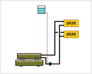
1.Single cooling water circulating system
Pumps in chilling water pipes pump water directly to the injection molding machine. Water will return to water chiller unite after going through the injection molding machine and be stored in water tank after being cooled. Cooling water is circulating and cooling in a circuit which consists of water tank, pump, mold and water chiller. Such kind of circuit is suitable for situations where a few machines are needed and required flow of system is not much (less than 1.5 times of rated flow of water chiller).

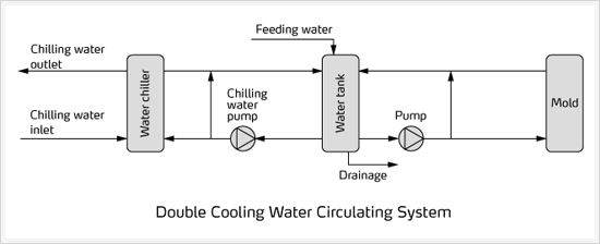
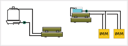
2.Double cooling water circulating system
When the system requires large flow (greater than 1.5 times of water chiller’s rated flow) or there are actual needs, it can adopt double water circulating system. Double cooling water system consists of inner chilling water circulating circuit and external chilling water circulating circuit. The inner one consists of water tank, pump and water chiller unit. In this circuit, the water chiller cools the water in water tank in cycles. The external one is made by water tank, pumps and onsite devices. In this circuit, water is directly pumped from water tank to all onsite devices. After taking away all heat of devices, the water will go back to water tank to mix again with chilling water coming from chilled water. The two cooling water circulating system are independent and have no influence on each other.
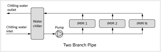
A.Two branch pipe
Two branch pipe of chilling water is suitable for situation where it requires small amount of chilling water or there is just a few injection molding machines. Diameters of two branch pipe require outlet pipes smaller and smaller. Both inlet and outlet of each machine is equipped with pressure adjusting valve to make the chilling water flow basically identical with pressure.
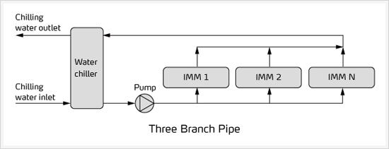
B.Three branch pipe
Return water pipe (three branch pipe) is suitable for situation where it requires large amount of chilling water or there are quite a few injection molding machines.
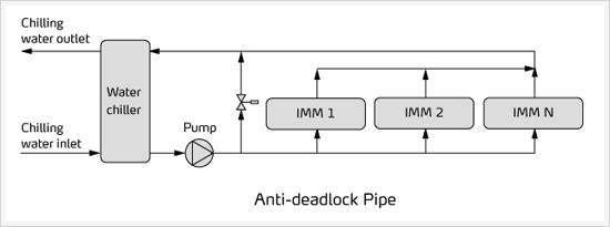
C.Anti-deadlock pipe
When all devices in central coolling water system are started up, chilling water flow in pipes and water pressure are of normal values. However, when some parts of devices are on and some parts are off, it will cause the water pressure of pipes to increase, which is not good for system safety. Anti-deadlock pipe is suitable for this situation. Mount devices similar to overflow valve to inlet and outlet of water chiller machine. When the water pressure goes up to set value, those devices will open automatically to make the water pressure not too high.
Notes
Generally, the cooling tower water shall be at the highest point of the whole system to ensure that all pipelines are full of circulation water to avoid problems, like rust and pressure fluctuation, which is caused by entering of air. In addition, it allows power of the cooling circulating pump whose head calculation just needs to be enough for overcoming pipe resistance and height of cooling tower water surface to spray header
For pipelines from water chiller to onsite devices, water in water tank shall be at the highest point of the whole system to make sure that all pipes are full of recycled water.
Considering chilling water’s characteristic of expansion and contraction, an expansion tank is necessary for a closed system. The expansion tank should be at the highest point of the whole system and its water fill up port should be connected with pump’s inlet.
Other accessory option
Electronic device for water treatment
For water supply and drainage system which uses water as medium, scaling, corrosion and microbial breeding always are the three main factors of damaging the system. Scaling will decrease efficiency of heat exchanging and increase energy consumption. Oxidization and corrosion will severely affect service lives of pipes and devices; it also will produce yellow rust water. Microbial breeding also will produce deposit and thus reduce water flow cross area which increase flow resistance and reduce efficiency of heat exchanging.
Electronic device for water treatment is also called electronic descaling and antiscaling device. This device which doesn’t require any chemicals is easy to mount and use. It is widely applied in boiler, central air-conditioner, heat-exchange equipment, looping water system and industry water treatment equipment, etc. It can effectively prevent and clear scales of physical, biological and chemical characteristics.
Flow control valve
Flow control valve is a multi-functional valve which controls flow by high precision guiding. It can keep the flow steady. It is suitable to limit excessive flow to a predetermined value for pipelines whose flow and pressure need to be controlled. It also can appropriately decrease the upstream pressure, which makes flow of main valve downstream won’t be affected even though the upstream pressure has changed.
Flow control valve is that kind of valve which controls flow of throttle valve by adjusting liquid resistance and thus to adjust moving speed of executive components, like hydraulic cylinder and hydraulic motor. It mainly includes throttle valve, speed control valve, overflow throttle valve and flow distributing and collecting valve, etc. It’s mounted horizontally.
Flow gauge
Flow gauge is for immediately detecting whether the system flow is normal and immediately inform maintenance personnel of that whether recycled water in the whole pipelines flow normally. It is also for preventing evaporator and onsite devices from damage when they are in the working condition of no water.
Pressure sensor
Pressure sensor is used the most in industrial practice. It is mounted to the water outlet of pump to ensure safe operation of system by immediately detecting that whether the system pressure is normal.
•Be able to precisely control chilling water temperature to adapt to different working conditions to meet demands.
•Compared with using of several single water chillers, central cooling water system can save cost.
•The main machine of central cooling system is usually placed outside the workshop, which can ensure low noise inside the workshop and good working environment.
•Save inner space of workshop. Water chiller of single machines is placed inside the workshop, which occupies too much precious space of factories. However, for central type, machines are usually placed in a particular area; few pipes can be seen, since all pipes are placed in the upper of the workshop or buried in the trench to make the workshop clean and tidy.
•Ensure continuous production even when the pump is with failure. The central cooling system is usually equipped with multiple pumps. When one of those pumps is broken, spare pumps can immediately be used for production, which ensures the continuous production.
System structure
Application of main water cooling machine
Application of main water cooling machine should be based on comprehensive consideration of factors, like the overall configurations of system, cooling requirements, the environmental and geographical conditions of workshop, equipment cost, and noise, etc.
Generally speaking, water cooled central water chiller is suitable for places with plenty of water and moderate ambient temperature. Water cooled central water chiller requires a cooling tower to work with for conveniently cooling water chiller unit with good cooling effect. However, it’s not applicable when environment is of too low temperature and easy to freeze. Air cooled central water chiller doesn’t require cooling tower. It cools refrigerant of high temperature via outside air so that it cuts the cost of cooling tower. It also can control cooling effect through controlling air volume when the ambient temperature is too low. However, its noise is larger than the water cooled one. Besides, it’s not suitable for situations where the ambient temperature is quite high.
Cooling capacity calculation, which is the start for calculation of all parameters, structure design and select of device, is the key point of central water cooling system. For injection plastics molding factories, cooling capacity calculation usually consists of two parts:
•Rapid cooling of molds
•Oil cooling of injection molding machine’s hydraulic system
Rapid cooling of molds
Most time of injection molding is for cooling molding products. Besides, all cooling water pipes of molds are placed quite near to the molding chamber of molding products to achieve high efficiency of cooling. Therefore, one mold is a heat exchanger which is used for taking heat away from molding products of high temperature by cooling water to improve molding speed. If molds are not equipped with hot runner system, it can calculate heat as the following formula:
Q1=M × S × T × δ
Q1=Refrigerant capacity(kcal/h)
M=Plastics consumption(kg/h)
S=Plastics specific heat(kcal/kg℃)
T=The temperature gap between the melt temperature and the product demolding temperature, which usually is 200℃.
δ=Safety factor
δ stands for safety factor, which is usually between 2.0 and 3.0. When choose air-cooled water chiller, it’s necessary to choose the bigger one on S. For bottle blowing machine, S may be 4.0.
If molds are equipped with hot runner, the refrigerating power should be increased accordingly. The increment is usually 0.6~0.8 times of hot runner power.
Cooling of injection molding machine
For injection molding machine, its refrigerant capacity is related to the motor power and molding cycle of hydraulic molding machine. It can be calculated according to the following formula:
Q2=P ×δ
Q2=Refrigerant capacity(kcal/h)
P=Motor power(kW)
δ=Factor
Usually, δ is ranging from 0.35 to 0.5. The value of 0.35 is suitable for common molding cycle (the molding cycle is greater than 10 seconds). The value of 0.5 or more is suitable for rapid molding cycle (the molding cycle is between 3 and 10 seconds).
Circular water capacity
The cooling water flow that a mold need is related to the heat that the mold needs to release and the temperature gap between inlet and outlet cooling water. It can be calculated according to the following formula:
Chilling water flow (Chilling water refers to the circular water of room temperature that the water chiller asks from the outside.):
L=(Q+P)÷(C×△t×D)÷1000
L=Required capacity of cooling water(m3/h)
P=Capacity of compressor (kW)
Q=Refrigerant capacity(kW/hr)
C=Specific heat of water 1kcal/(kg•℃)
△t=The temperature gap between inlet and outlet water, 5℃
D=Density of water kg/L
the cold water flow (cold water refers to the circular water of low temperature that the water chiller supplies for onsite production)
L=Q÷(C×△t×D)÷1000
L=Required flow of chilling water(m3/h)
Q=Refrigerant capacity(kW/hr)
C=Specific heat of water 1kcal/(kg•℃)
△t=The temperature gap between inlet and outlet water, 5℃
D=Density of water kg/L
Temperature preservation water tank
In cooling water system, the temperature preservation water tank is for storing water to ensure enough water for system running. It’s also for storing energy: the bigger the water tank is, the more energy it stores. What’s more, it allows the water chiller not to start up frequently to save energy and electricity.
The temperature preservation water tank doesn’t bear pressure, but just bear the weight of chilling water inside it and standard air pressure. Temperature preservation is achieved by making use of a medium (like polyurethane foam) to separate the water tank from the outside world, which lower the temperature in some certain conditions of environmental temperature.
The structure of temperature preservation water tank usually consists of inner water tank, temperature insulating layer and shell. Inner water tank usually consists of stainless steel 304, enamel inner tank, inner tank of slush molding powder (crystal inner tank). Service life of the water tank depends on raw material and process technology. Generally speaking, process technology of stainless steel is quite simple; welding process is the main one need to solve.
The capacity of temperature preservation water tank in cooling water system is usually not less than 3 times of pump’s rated flow. Refer to the following formula:
Water tank’s capacity Q(L)≥ pump’s rated flow(L/min)×3
Cooling tower
Nominal water flow of cooling tower should meet the required cooling water capacity for water chiller unit. Meanwhile, the inlet and outlet water temperature of cooling tower should coincide respectively with the ones of water chiller unit’s condenser. Check the product sample book about thermo performance curve of chilling water to confirm whether the actual water flow meets the water chiller’s requirement toward chilling water. The select of cooling tower usually depends on cooling water capacity. Refer to the following formula:
Water flow of cooling tower(m3/h)= total cooling capacity(kW)×860(kcal/h)÷3000 × 1.2
Pump
Generally, central cooling system is a water system with several pumps to immediately restore water supply when one pump is broken, which can ensure the minimal failure recovery cycle and continuous production.
The select of pumps should be based on the placement of pipes at production site, line wear and parameters of required pressure and flow of all devices.
Pipelines
1.Single cooling water circulating system
Pumps in chilling water pipes pump water directly to the injection molding machine. Water will return to water chiller unite after going through the injection molding machine and be stored in water tank after being cooled. Cooling water is circulating and cooling in a circuit which consists of water tank, pump, mold and water chiller. Such kind of circuit is suitable for situations where a few machines are needed and required flow of system is not much (less than 1.5 times of rated flow of water chiller).
2.Double cooling water circulating system
When the system requires large flow (greater than 1.5 times of water chiller’s rated flow) or there are actual needs, it can adopt double water circulating system. Double cooling water system consists of inner chilling water circulating circuit and external chilling water circulating circuit. The inner one consists of water tank, pump and water chiller unit. In this circuit, the water chiller cools the water in water tank in cycles. The external one is made by water tank, pumps and onsite devices. In this circuit, water is directly pumped from water tank to all onsite devices. After taking away all heat of devices, the water will go back to water tank to mix again with chilling water coming from chilled water. The two cooling water circulating system are independent and have no influence on each other.
Two branch pipe of chilling water is suitable for situation where it requires small amount of chilling water or there is just a few injection molding machines. Diameters of two branch pipe require outlet pipes smaller and smaller. Both inlet and outlet of each machine is equipped with pressure adjusting valve to make the chilling water flow basically identical with pressure.
B.Three branch pipe
Return water pipe (three branch pipe) is suitable for situation where it requires large amount of chilling water or there are quite a few injection molding machines.
When all devices in central coolling water system are started up, chilling water flow in pipes and water pressure are of normal values. However, when some parts of devices are on and some parts are off, it will cause the water pressure of pipes to increase, which is not good for system safety. Anti-deadlock pipe is suitable for this situation. Mount devices similar to overflow valve to inlet and outlet of water chiller machine. When the water pressure goes up to set value, those devices will open automatically to make the water pressure not too high.
Generally, the cooling tower water shall be at the highest point of the whole system to ensure that all pipelines are full of circulation water to avoid problems, like rust and pressure fluctuation, which is caused by entering of air. In addition, it allows power of the cooling circulating pump whose head calculation just needs to be enough for overcoming pipe resistance and height of cooling tower water surface to spray header
For pipelines from water chiller to onsite devices, water in water tank shall be at the highest point of the whole system to make sure that all pipes are full of recycled water.
Considering chilling water’s characteristic of expansion and contraction, an expansion tank is necessary for a closed system. The expansion tank should be at the highest point of the whole system and its water fill up port should be connected with pump’s inlet.
Other accessory option
Electronic device for water treatment
For water supply and drainage system which uses water as medium, scaling, corrosion and microbial breeding always are the three main factors of damaging the system. Scaling will decrease efficiency of heat exchanging and increase energy consumption. Oxidization and corrosion will severely affect service lives of pipes and devices; it also will produce yellow rust water. Microbial breeding also will produce deposit and thus reduce water flow cross area which increase flow resistance and reduce efficiency of heat exchanging.
Electronic device for water treatment is also called electronic descaling and antiscaling device. This device which doesn’t require any chemicals is easy to mount and use. It is widely applied in boiler, central air-conditioner, heat-exchange equipment, looping water system and industry water treatment equipment, etc. It can effectively prevent and clear scales of physical, biological and chemical characteristics.
Flow control valve
Flow control valve is a multi-functional valve which controls flow by high precision guiding. It can keep the flow steady. It is suitable to limit excessive flow to a predetermined value for pipelines whose flow and pressure need to be controlled. It also can appropriately decrease the upstream pressure, which makes flow of main valve downstream won’t be affected even though the upstream pressure has changed.
Flow control valve is that kind of valve which controls flow of throttle valve by adjusting liquid resistance and thus to adjust moving speed of executive components, like hydraulic cylinder and hydraulic motor. It mainly includes throttle valve, speed control valve, overflow throttle valve and flow distributing and collecting valve, etc. It’s mounted horizontally.
Flow gauge
Flow gauge is for immediately detecting whether the system flow is normal and immediately inform maintenance personnel of that whether recycled water in the whole pipelines flow normally. It is also for preventing evaporator and onsite devices from damage when they are in the working condition of no water.
Pressure sensor
Pressure sensor is used the most in industrial practice. It is mounted to the water outlet of pump to ensure safe operation of system by immediately detecting that whether the system pressure is normal.
Special Reports
- Application of Plastics Auxiliary Equipment
- The Application of Honeycomb Dehumidifier
- Modular Application of Dehumidifying Dryer
- Temperature Control of Hot Runner System
- System or Individual Setup
If you want to read other articles, back to2013 Quarter 4 Issue 17.