

What Is a Central Conveying System? Components, Airflow Path and the Five Inputs That Decide Its Size
A central conveying system moves resin from bulk storage (silos, day bins or bulk bag unloaders) to every processing machine on the floor through one shared pipeline network, driven by a central vacuum station rather than a motor mounted on each machine.
Size that station wrong and one of two things happens: machines at the far end of the plant starve whenever several call for material at once, or an oversized system pays for air it never uses and shears pellets into fines on the way. Five inputs decide the size, and you can settle all five on your own floor before you talk to a supplier.
What a Central Conveying System Is, and What It Replaces
A central conveying system replaces the self-contained loader on each machine with one vacuum station, one filtration stage and one control cabinet serving the whole floor. The machines keep their receiving hoppers. Everything upstream of those hoppers is what changes.
Centralizing buys three things that are hard to get any other way. Dust is separated and collected at one point instead of at twenty filter housings. Material reaches the presses without anyone carrying a sack across the shop floor. Storage also stops being tied to a particular machine, so switching a press to a different resin becomes a routing decision rather than a physical job.
The trade is that one station now serves the whole plant, which turns sizing into a plant-level decision rather than a machine-level one. Everything below follows from that single change. If you want the system view across storage, conveying, drying and dosing rather than conveying alone, our central material handling system page covers the full plant layout.
The Six Component Groups, and What Each One Solves
Six component groups make up a central conveying system, and each one exists to solve a problem that appears the moment you stop putting a loader on every machine. The list below follows the material from storage to the press:
Bulk storage: silos, day bins and bulk bag unloaders
This is where a plant decides how much resin it wants sitting on site and in what form it arrives. Outdoor silos suit high-volume single-resin plants; assembled and fabric-flex silos suit plants that cannot pour a foundation or that change resin often; a bulk bag discharge station suits plants buying in 1-tonne bags.
We have covered the bulk bag end of this in more detail in automated bulk bag unloading and bulk bag unloader features.
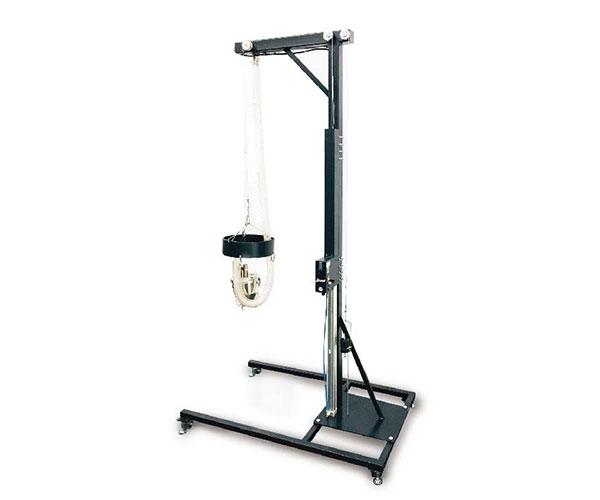
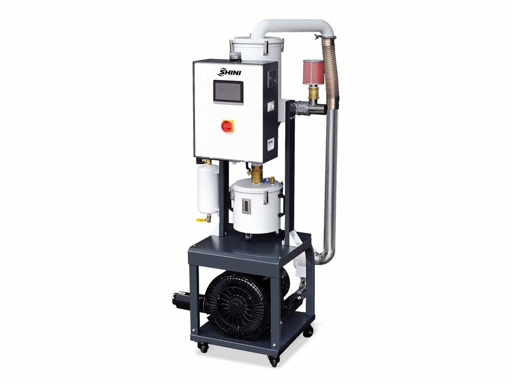
The central vacuum station
One or more central vacuum generators produce the negative pressure that carries material along the pipeline. Centralizing this is the change that makes everything else possible, because a single station can be sized for the plant's real simultaneous demand instead of for the sum of every machine's peak.
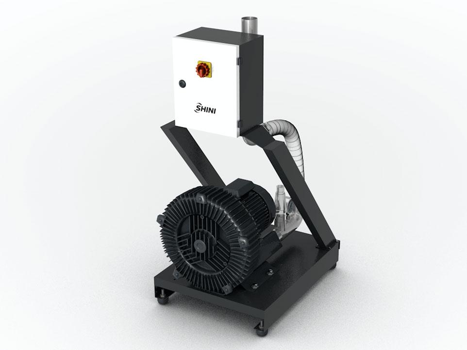
Pipelines, valves and the material selection station
The pipeline is shared, so something has to decide which resin travels to which machine and when. That is the job of the central material distribution station, which opens a path between one source and one requesting machine and closes the rest. A manual distribution station using quick couplers is enough for small systems; larger plants use the automatic version driven from the control board.
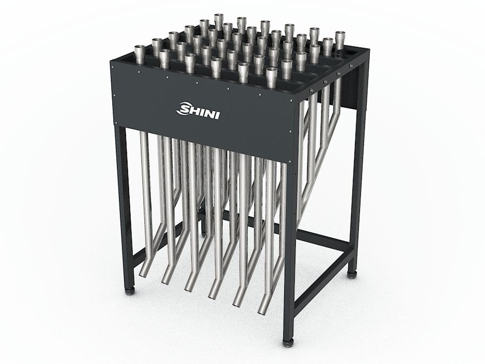
Filtration, and the separate job of de-dusting the material
Two different dust problems live in a central system, and they need different equipment. Fines carried in the airstream will reach the blower unless something stops them, which is what a central filter is for: it sits upstream of the pump and protects it.
Dust clinging to the resin itself is a product-quality problem, not a machine-protection one, and it is handled by a dedicated de-dusting unit (SDS) that passes the material through a dust chamber while an ion blower neutralizes the static charge holding dust to the pellets. Its stated separation efficiency is 80%, and it matters most on PET, PA and PC.
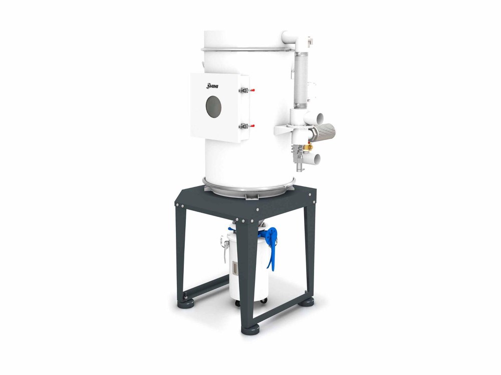
Receiving stations on the machine
Each press keeps a hopper receiver, the component our product pages call a central vacuum hopper loader (SCAL). It calls for material when its level drops and stops when it is full. A material consumption monitor (SMM) on the receiver turns that same signal into a record of how much each machine actually used.
Central control
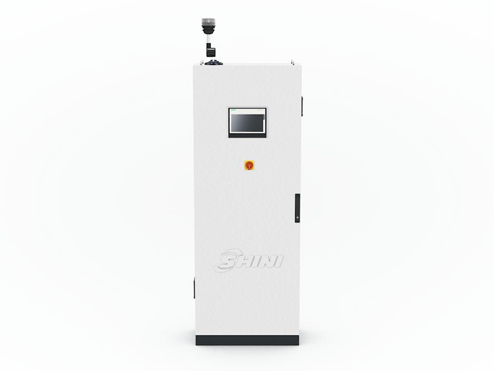
A central control station built around a programmable logic controller (PLC) and a human-machine interface (HMI) handles routing, alarms and fault logging for the whole loop. On a plant with dozens of presses this is also the only practical place to see what the system is doing.
Vacuum is not the only way to move material. For some distances and materials a positive pressure conveying arrangement is the better fit, and that choice belongs in the sizing conversation rather than in the component list.
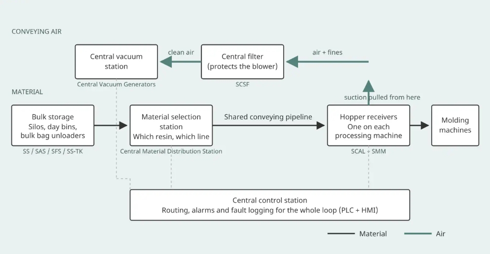
Material moves left to right, from bulk storage through the selection station and the shared pipeline to a hopper receiver on each machine. Conveying air travels the opposite way, from the receivers through the central filter to the vacuum station that is pulling the whole loop.
How One Transfer Actually Happens, Step by Step
A transfer starts at the machine, not at the silo. Following one request end to end is the fastest way to see why each component group is where it is:
A machine asks for material
The hopper receiver on the press detects that its level has dropped and sends a request to the control station. On plants running several grades, the request carries the material identity as well as the machine address.
The control station picks a route
It opens the valve at the selection station that connects the requested source to that machine, and keeps the rest closed. Nothing else on the network can be served on that line until the cycle ends.
The vacuum station pulls
Negative pressure at the receiver draws air through the pipeline, and the airstream lifts and carries the pellets from the silo or bin to the press. Conveying speed matters here: too slow and material settles in the line, too fast and it shears. Our systems use an air refilling adjustment on the line to hold that balance, which is what keeps angel hair and dust generation down when the same line serves different materials.
Fines come out of the airstream before the pump
The central filter takes them out upstream of the blower, so that by the time the air reaches the pump it should be carrying nothing.
Material drops, and the line clears
The receiver fills, the vacuum cycle stops and the material falls into the machine hopper. On systems configured for it, a reverse purge then clears residual pellets and dust from the line so the next cycle starts clean.
Two of those five steps are where most plant-level problems show up later. Step 2 decides whether a resin change is a software action or a manual one, and step 5 decides how much of the previous material is still in the line when the next one arrives.
When a Central System Beats Machine-Side Loaders
There is no single machine count at which a central system starts to pay, because four variables move that line in different directions. Counting presses alone will give you the wrong answer on any plant that changes material often.
How many machines draw at the same time
Twenty presses that never call together need less capacity than eight that do.
How often you change material
Frequent changes push the economics toward a central system quickly, because each change on machine-side loaders is manual labor and each one is a chance to mix grades.
How many resins you run
More grades means more sources and more selection-station capacity, which raises the entry cost but also raises what centralizing saves.
What material handling costs you today
The people currently carrying sacks, cleaning filters and clearing blockages are the comparison, not the loaders themselves.
The top of the range is not theoretical. A plant we commissioned in Guangdong, China integrated 112 injection molding machines on one central system, with a combined material consumption of about 1.2 tonnes per hour and a maximum conveying run of 135 m horizontally and 3.5 m vertically, covering storage, central conveying, drying and mixing together.
Where a plant sits between a handful of presses and a hundred is a question of those four variables, and answering it is the same exercise as sizing the system.
The Five Inputs That Decide How the System Gets Sized
Five numbers set the pipe diameter and the vacuum capacity, and they interact: change one and the other four move. Gather them before you ask anyone to quote, because a quote built on the wrong throughput figure is not a quote you can compare.
Conveying distance
Horizontal run, vertical lift and the number of bends, not just the straight-line distance across the plant. The Guangdong system above runs 135 m horizontally and 3.5 m vertically; a shorter run with more bends can be the harder job of the two.
Combined throughput per hour
The plant total, not the largest machine. That 112-machine plant draws about 1.2 tonnes per hour in total, and the total is what the vacuum station has to sustain.
Material type and form
Pellet, powder, regrind and hygroscopic materials behave differently in a line. Regrind and fines-heavy material change both the filtration duty and the conveying speed you can use without generating more dust.
Number of machines and simultaneous demand
How many receivers can call at once is the figure that sizes the pump, and it is almost always lower than the machine count. Getting this wrong in either direction is the most common sizing error we see.
Changeover frequency
How often material changes decides whether the plant needs dedicated lines for some grades or whether a shared line with a purge cycle is enough. This one is usually the reason a layout that looks oversized on paper is actually correct.
Read together, the five inputs do not all push on the same part of the system:
| Input | What it mainly drives |
|---|---|
| Conveying distance and bends | Pipe diameter and the vacuum level needed at the far end |
| Combined throughput per hour | Vacuum station capacity |
| Material type and form | Conveying speed, filtration duty, and whether positive pressure fits better |
| Simultaneous demand | Pump sizing, and how many lines the plant needs |
| Changeover frequency | Dedicated versus shared lines, and purge configuration |
Those five figures interact, so sending them together gets you a usable answer faster than asking one at a time. We can run the layout and vacuum station sizing from them directly.
Changeover and Line Cleaning
On a shared pipeline, the material left in the line after a transfer is the material that arrives at the next machine. That is the whole of the changeover problem, and it is why purge behavior belongs in the specification rather than in commissioning.
A reverse purge cycle clears residual pellets and dust from the line between transfers. How thoroughly it needs to work depends on what you are running: a color change on a transparent part tolerates far less carryover than a change between two natural grades of the same polymer. Plants with a small number of critical grades often dedicate a line to them rather than relying on purging at all.
If you are specifying a system now, three questions will tell you most of what you need: how the supplier purges a shared line, what carryover is expected after a purge, and at what point they recommend a dedicated line instead.
PET Preform Plants and General Injection Plants
A PET preform plant runs the same components in a different arrangement, because polyethylene terephthalate (PET) arrives at the press hot and rewets easily. Three things change as a result.
Material contact surfaces and the filter device are stainless steel throughout, so that nothing contaminates the resin on its way to the press. High-temperature PET conveying uses a water-cooling function on the line, which our PET systems were designed around. The conveying to the machine hopper is also arranged as a closed loop across two stages, which reduces heat dissipation and cuts the risk of the material rewetting between the dryer and the press.
A general injection plant running several unrelated grades has the opposite priority: more sources, more selection-station capacity and more attention to purge behavior, with less concern about heat loss in the final meters. Our PET preform system page covers the crystallizer, dryer and blender side of that configuration.
Frequently Asked Questions
What are the different types of conveying systems?
For plastics, the practical division is by how the material is moved and by how many machines share the equipment. Vacuum (negative pressure) conveying is the most common in molding plants; positive pressure conveying suits some materials and longer runs; mechanical conveying such as a flexible screw feeder handles short transfers and difficult materials. Each of those can be arranged as a self-contained loader on one machine or as a central system serving many.
What is the definition of a conveying system?
A conveying system is the equipment that moves raw material from where it is stored to where it is processed, together with the controls that decide when and where it moves. In a plastics plant that means resin traveling from a silo, bin or bag to the hopper on a molding or extrusion machine.
What are the different types of pneumatic conveying systems?
Pneumatic conveying is usually split into dilute phase and dense phase. Dilute phase suspends material in a fast airstream and covers most resin pellet applications, including central conveying in molding plants. Dense phase moves material more slowly at higher pressure in slugs, which suits fragile or abrasive materials where shearing is the concern.
Talk to Us Before You Pick a Pipe Size
This page stops short of giving you a pipe diameter and a pump model, because those two numbers are not general knowledge. They are the output of your plant's figures, and distance, throughput, material form, simultaneous demand and changeover frequency all move them together.
Send us those five figures and our engineers will come back with a proposed pipe layout and vacuum station size. Our contact form has one free-text box, so put them straight into Comments:
- Total conveying distance: horizontal, vertical, and roughly how many bends
- Combined throughput in kg/hr across the plant
- Material type and form: pellet, powder, regrind, hygroscopic
- Number of machines, and how many can call for material at the same time
- How often you change material
Already running a Shini central system and looking to extend it or replace a component? Please contact us today.